风机流量调节阀
AIR-BLOWER REGULATING VALVE
风机流量调节阀广泛适用于 建材、玻璃、矿山、电力、轻工、造纸等行业 的风机入口及通风管道,与风机配套使用,对管路中流量根据工况的不同需要进行调节,以满足管道工艺运行的需要。
This valve is widely used at the venting pipe and air-blower inlet in building material, glass, mining, power, light industry and papermaking departments. It is equipped with air-blower to adjust flow in pipe by the different working conditions and meet the demand of pipe technology operation.
结构特点:
Structure characteristic:
风机流量调节阀设计新颖、结构合理,调节板采用多叶、多轴式,使气流均匀分流,流阻小,启闭力矩小,动作灵活可靠,各传动部位采用润滑轴承,运转灵活,摩擦系数小调节轻松自如,能有效地控制气体流量,稳定风机的输出曲线,充分利用能源使工作系统达到理想状态,是各种风管系统中理想的调节设备 。
The valve has the features of novel design and compact structure. Its regulating disc adopts multi-blade and multi-axle, which can shunt airflow. Flow resistance and open-close torque is little and operation is reliable. The lubricating bearing of transmission part is flexible on operation and handy of regulating with little coefficient of friction. It can control the airflow effectively and stabilize the output curve of air-blower and make the working system in optimal state by making full use of energy. It is the ideal regulating device in all kinds of air piping system.
性能参数:
Performance parameter:
公称压力 Nominal pressure |
介质流速 Medium velocity |
泄漏率 Leakage ratio |
适用温度 Suitable temperature |
适用介质 Suitable medium |
0.05MPa |
≤ 20 m/s |
≤ 1.5% |
≤ 300 ℃ |
空气、粉尘气体等 Air, gas with powder etc |
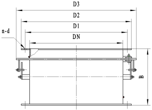
外形图:
Appearance figure :

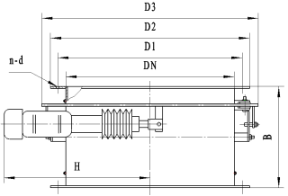
外形图:
Appearance figure :

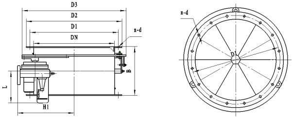
外形图: 外形 连接示意 图:
Appearance figure : Appearance figure :

外形连接尺寸:
Appearance joint dimensions:
DN |
D1 |
D2 |
D3 |
B |
n-d |
片数 |
H |
H1 |
L |
电 动 推 杆 |
电 动 执行器 |
280 |
306 |
324 |
480 |
250 |
8- Φ 10 |
4 |
695 |
305 |
380 |
DT Ⅱ A100-M P : 0.37 KW |
DKJ-210 T : 100N·m P : 0.025KW |
310 |
330 |
350 |
500 |
250 |
12- Φ 10 |
4 |
695 |
315 |
380 |
||
320 |
350 |
367 |
520 |
250 |
16- Φ 8 |
4 |
695 |
325 |
380 |
||
360 |
394 |
416 |
580 |
300 |
16- Φ 8 |
4 |
695 |
355 |
380 |
||
365 |
385 |
410 |
580 |
300 |
12- Φ 10 |
4 |
695 |
355 |
380 |
||
400 |
440 |
462 |
660 |
250 |
16- Φ 8 |
6 |
790 |
380 |
460 |
DT Ⅱ A300-M P : 0.55 KW |
DKJ-310 T : 250N·m P : 0.065KW |
420 |
445 |
470 |
650 |
250 |
16- Φ 10 |
6 |
790 |
385 |
460 |
||
450 |
490 |
512 |
700 |
250 |
16- Φ 10 |
6 |
790 |
405 |
460 |
||
470 |
495 |
520 |
720 |
300 |
16- Φ 10 |
6 |
790 |
415 |
460 |
||
500 |
550 |
572 |
780 |
300 |
16- Φ 10 |
6 |
790 |
445 |
460 |
||
520 |
545 |
570 |
800 |
300 |
16- Φ 10 |
6 |
790 |
455 |
460 |
||
600 |
650 |
576 |
880 |
300 |
16- Φ 10 |
8 |
900 |
495 |
510 |
DT Ⅱ A500-M P : 0.75 KW |
DKJ-410 T : 600N·m P : 0.16KW |
620 |
650 |
685 |
900 |
300 |
16- Φ 10 |
8 |
900 |
510 |
510 |
||
800 |
860 |
910 |
1150 |
350 |
12- Φ 12 |
8 |
900 |
635 |
510 |
||
1000 |
1065 |
1110 |
1350 |
350 |
16- Φ 14 |
12 |
900 |
735 |
510 |
||
1200 |
1270 |
1330 |
1580 |
350 |
12- Φ 14 |
12 |
1030 |
850 |
650 |
DT Ⅱ A700-M P:0.75 KW |
DKJ-510 T : 1600N·m P : 0.4KW |
1600 |
1660 |
1700 |
2000 |
400 |
28- Φ 14 |
16 |
1030 |
1070 |
650 |
||
2000 |
2070 |
2120 |
2420 |
450 |
32- Φ 14 |
16 |
1030 |
1280 |
650 |